Section 12.8 Logic Circuit Minimization
¶Let's start with a logic circuit and see how the laws of boolean algebra can help us simplify it.
Example 12.8.1. Simplification of a circuit.
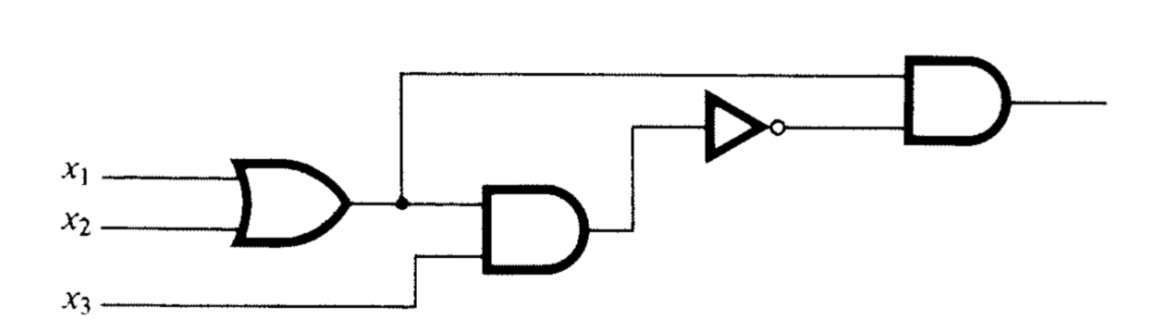
Consider the circuit in Figure 12.8.2. As usual, we assume that three inputs enter on the left and the output exits on the right.
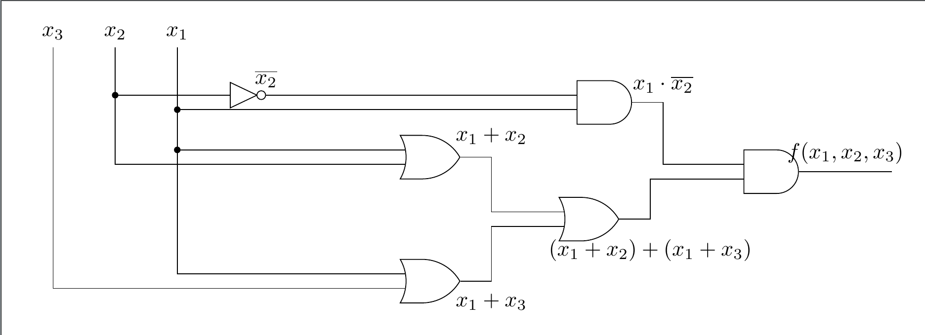
If we trace the inputs through the gates we see that this circuit realizes the boolean function
We simplify the boolean expression that defines \(f\text{,}\) simplifying the circuit in so doing. You should be able to identify the laws of Boolean algebra that are used in each of the steps. See Exercise 12.7.1.
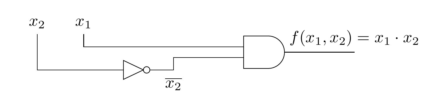
Therefore, \(f\left(x_1, x_2, x_3\right)=x_1 \cdot \overline{x_2}\text{,}\) which can be realized with the much simpler circuit in Figure 12.8.3, without using the input \(x_3\text{.}\)
Next, we start with a table of desired outputs based on three bits of input and design an efficient circuit to realize this output.
Example 12.8.4.
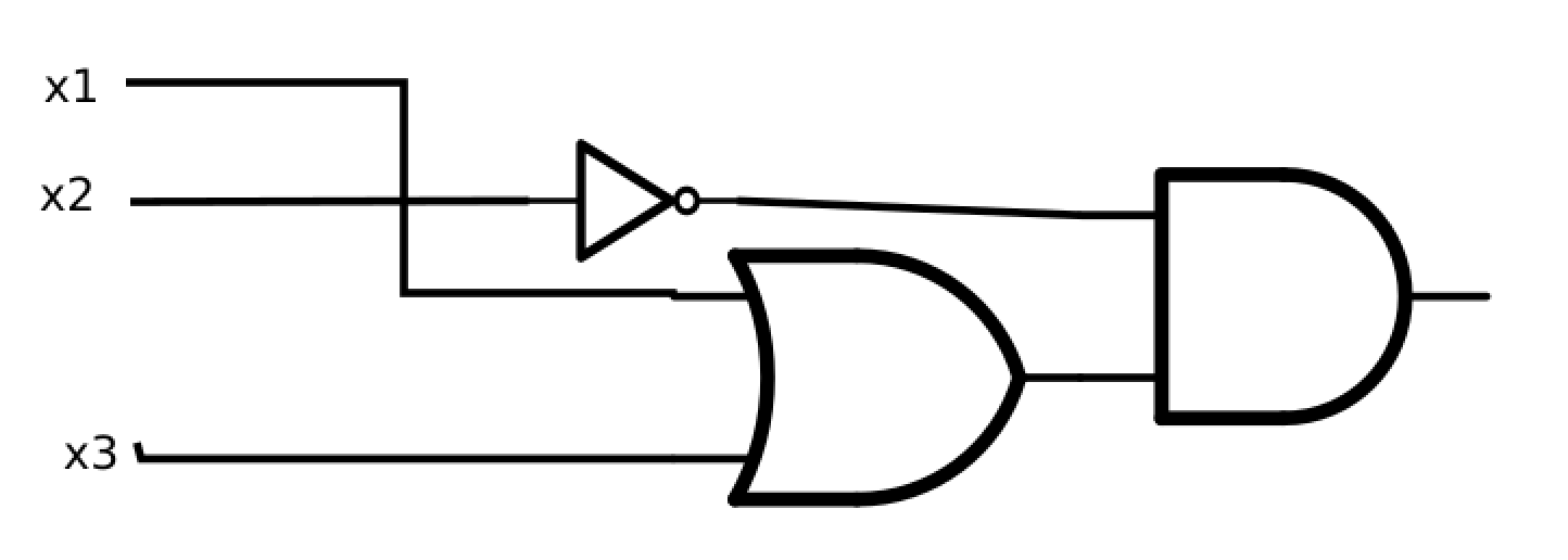
Consider the following table of desired outputs for the three input bits \(x_1, x_2, x_3\text{.}\)
| \(x_1\) | \(x_2\) | \(x_3\) | \(f(x_1,x_2,x_3)\) |
| 0 | 0 | 0 | 0 |
| 0 | 0 | 1 | 1 |
| 0 | 1 | 0 | 0 |
| 0 | 1 | 1 | 0 |
| 1 | 0 | 0 | 1 |
| 1 | 0 | 1 | 1 |
| 1 | 1 | 0 | 0 |
| 1 | 1 | 1 | 0 |
A circuit diagram for this function is Figure 12.8.6. But is this the simplest circuit that realizes the table? See Exercise 12.8.3.
Exercises Exercises for Section 12.8
¶1.
List the laws of boolean algebra that justify the steps in the simplification of the boolean function \(f\left(x_1, x_2, x_3\right)\) in Example 12.8.1. Some steps use more than one law.
Associative, commutative, and idempotent laws.
Distributive law.
Idempotent and complement laws.
Null and identity laws
Distributive law.
Null and identity laws.
2.
Write the following Boolean expression in the notation of logic design.
3.
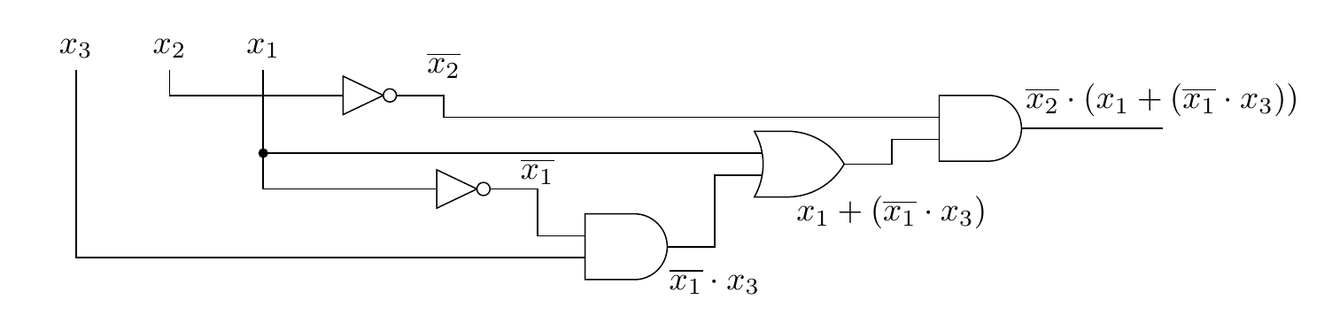
Find a further simplification of the boolean function in Example 12.8.4, and draw the corresponding gate diagram for the circuit that it realizes.
A simpler boolean expression for the function is \(\overline{x_2} \cdot (x_1 + x_3)\text{.}\)
4.
Consider the switching circuit in Figure 12.8.8.
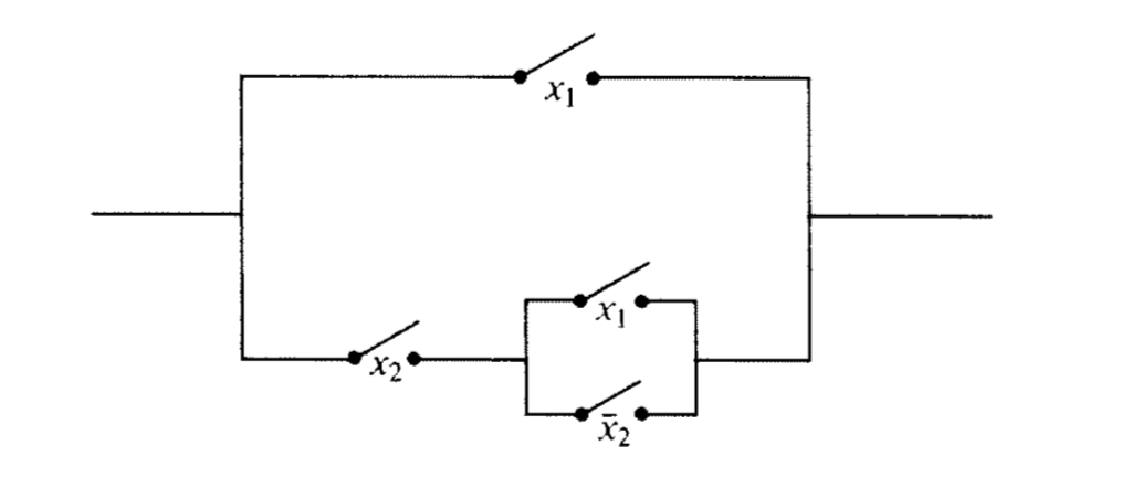
Draw the corresponding gate diagram for this circuit.
Construct a table of outputs for each of the eight inputs to this circuit.
Determine the minterm normal of the Boolean function based on the table.
Simplify the circuit as much as possible.
5.
Consider the circuit in Figure 12.8.9.
Trace the inputs though this circuit and determine the Boolean function that it realizes.
Construct a table of outputs for each of the eight inputs to this circuit.
Find the minterm normal form of \(f\text{.}\)
Draw the circuit based on the minterm normal form.
Simplify the circuit algebraically and draw the resulting circuit.
6.
Consider the Boolean function \(f\left(x_1, x_2, x_3, x_4\right)=x_1 + \left(x_2 \cdot \left(\overline{x_1} + x_4\right) + x_3 \cdot \left(\overline{x_2} + \overline{x_4}\right)\right).\)
Simplify \(f\) algebraically.
Draw the gate diagram based on the simplified version of \(f\text{.}\)